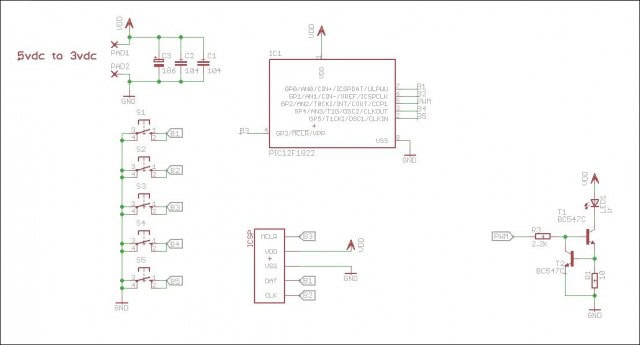
Interesante mando infrarrojos RC5 realizado con un pequeño PIC12F que nos envía el amigo Akenafab.
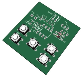
Les comparto este proyectito totalmente funcional con el pic12F1822 ( Una maravilla de uC).
Lo he probado en 3 televisores philips y anda al 100%.
Adjunto código fuente, esquema electrónico, pcb y simulación en proteus vsm. Están todos los archivos en este enlace.
El programa está realizado con PIC C de CCS version 4.128; versiones anteriores tenían error con función delay, manejo de registros y otras cosas sospechosas.
Las características principales son:
- PIC 12F1822
- 5 botones ( ON/OFF , Vol+ , Vol- , Ch+ , Ch – )
- Protocolo RC5 de Philips
- Uso del toggle bit para detectar la pulsación continuada
El micro se queda en reposo mientras no se presione tecla alguna, si se presiona alguna tecla envía el código correspondiente.
Si se mantiene presionada la misma tecla sigue enviando el código tras X tiempo como marca el protocolo.
Al soltar la tecla modifica el toggle bit para ser reconocido nuevamente por el receptor como nueva tecla.
Regresa a modo reposo (sleep).
Se hace uso de componentes mínimos , se activan Resistencias de pull-up internas.
Puede omitirse el transistor pero la distancia de transmisión disminuye.
El programa todavía no esta del todo optimizado para bajo consumo, ya que uso el oscilador a 32MHZ. Solo habría que bajarlo y modificar la configuración de puertos, etc…
// IR Remote Control for Philips TV using RC5 protocol
//——————————————————————–
//AKENAFAB
//http://www.todopic.com.ar/foros/
//——————————————————————–
// 14bits wide ->|START|START|TOGGLE|5BIT ADDRESS|6BIT COMMAND|<- // 36KHz Carrier Frequency //——————————————————————– #include <12F1822.h>
//——————————————————————–
#FUSES INTRC_IO,NOCLKOUT,NOWDT,PUT,NOMCLR,BROWNOUT,BORV25,PROTECT,CPD,NOIESO,NOFCMEN,NOLVP
#use delay(clock=32M)
#use fast_io(A)
#zero_ram
//——————————————————————–
#byte IOCAP = 0x391 //ON rising-edge interrupt
#byte IOCAN = 0x392 //ON falling-edge interrupt
#byte IOCAF = 0x393 //IOC FLAG register
#byte INTCON = 0x0B //Interrupt Control Register
//——————————————————————–
//——— ————————————————–
#define IR_LED PIN_A2
#define ON 1
#define OFF 0
//——————————————————————–
long pwm_duty_cycle=416; //PWM MAX = 832 , PWM DUTY SET to 50%
char button_pressed;
char new_button_pressed;
char RA_FLAG;
//——————————————————————–
long commands[5]={ 0b11000000001100,0b11000000010000,0b11000000010001,
0b11000000100000,0b11000000100001};
char command_index;
/*
long TV_STAND_BY =0b11000000001100; // ON-OFF
long TV_VOL_UP =0b11000000010000; // Volumen +
long TV_VOL_DOWN =0b11000000010001; // Volumen –
long TV_CH_UP =0b11000000100000; // Channel +
long TV_CH_DOWN =0b11000000100001; // Channel –
*/
//——————————————————————–
void ir_transmit(char command); // Transmits the COMMAND
void PWM_pulse(char state); // Controls the PWM output

void main(){
//——————————————————————-
setup_comparator(NC_NC); // COMPARATOR OFF
SETUP_ADC(ADC_OFF); // ADC OFF
SETUP_ADC_PORTS(NO_ANALOGS); // NO ANALOG PINS

output_A(0x00); // OutputLatch
set_tris_A(0B111011); //
// RA0=INPUT
// RA1=INTPUT
// RA2=IR_LED OUTPUT
// RA3=INPUT
// RA4=INPUT
// RA5=INPUT

PORT_A_PULLUPS(0b111011); // Internal pull-ups resistor enabled

//——————————————————————–
enable_interrupts(INT_RA); //Interrupt On-Change on PORT
IOCAN=0b111011; //Interrupt On-Change RA High to Low
IOCAP=0b000000;
bit_clear(INTCON,0); //Clearing IOCF flag bit
IOCAF=0; //Clearing IOC flags

enable_interrupts(GLOBAL); //Global interrupts enabled
//——————————————————————–
//——— MAIN PROGRAM —————————–\\\\
while(1){

sleep();

if(RA_FLAG==TRUE){ //If any button was pressed
RA_FLAG=FALSE; //Resefting the RA FLAG for the new incoming data detection

button_pressed=~button_pressed; //Masking buttons
button_pressed&=0b111011; //getting the pressed button

switch(button_pressed){

case 0x01: command_index=0; //Button 0
break;
case 0x02: command_index=1; //Button 1
break;
case 0x08: command_index=2; //Button 2
break;
case 0x10: command_index=3; //Button 3
break;
case 0x20: command_index=4; //Button 4
break;

}//switch button-command

ir_transmit(command_index); //Transmiting selected code

IOCAF=0; //Clearing IOC flags
bit_clear(INTCON,0); //Clearing IOCF Global flag big
bit_set(INTCON,3); //Enabling IOC interrupt
}//IF-RA FLAG

}////end while
}// main

//——– INTERRUPTS ————————————-
#INT_RA
void port_change(){
IOCAF=0; //Clearing IOC flags
bit_clear(INTCON,0); //Clearing IOCF Global flag bit
bit_clear(INTCON,3); //Disabling IOC interrupt to avoid reentrance

button_pressed=input_A(); //Reading PORT

RA_FLAG=TRUE; //Botton pressed Flag
}//Interrupt On Change
//——————————————————————–
//——– FUNCTIONS ————————————–
void ir_transmit(char index){ //Transmits the IR command
char x;
char rc5_bit;

do{ //At Least once transmitted
rc5_bit=13; //MSB firts
for(x=0;x<14;x++){ //Transmiting 14 bits if(bit_test(commands[index],rc5_bit)==1){ //Transmiting _01_ PWM_pulse(OFF); delay_us(880); PWM_pulse(ON); delay_us(880); } else { PWM_pulse(ON); //Transmiting _10_ delay_us(880); PWM_pulse(OFF); delay_us(880); } rc5_bit–; }//for x address PWM_pulse(OFF); delay_ms(114); //Delay between same command new_button_pressed=input_A(); new_button_pressed=~new_button_pressed; new_button_pressed&=0b111011; }while(new_button_pressed==button_pressed); //While the same button stays pressed //Updating Toggle-bit if(bit_test(commands[index],11)==0)bit_set(commands[index],11); else bit_clear(commands[index],11); }//ir-transmit function //——————————————————————– void PWM_pulse(char state){ //Controls the PWM output if(state==ON){ SETUP_CCP1(CCP_PWM); // PWM SETUP_TIMER_2(T2_DIV_BY_1, 221,1); // Frequency = 36KHz – SET_PWM1_DUTY(pwm_duty_cycle); // Duty cycle = 50% – } else{ SETUP_CCP1(CCP_OFF); // PWM OFF SETUP_TIMER_2(T2_DISABLED, 221,1); // Timer2 disabled SET_PWM1_DUTY(pwm_duty_cycle); // Duty cycle = 50% – JUST FOR MATCHING TIME output_low(pin_A2); // Ensures the output is on LOW state }//else }//function PWM PULSE //——————————————————————–
Espero tus comentarios en el foro.